10+ logic block diagram
Supervisory control and data acquisition SCADA is a control system architecture comprising computers networked data communications and graphical user interfaces for high-level supervision of machines and processes. A circuit diagram wiring diagram electrical diagram elementary diagram electronic schematic is a graphical representation of an electrical circuitA pictorial circuit diagram uses simple images of components while a schematic diagram shows the components and interconnections of the circuit using standardized symbolic representations.
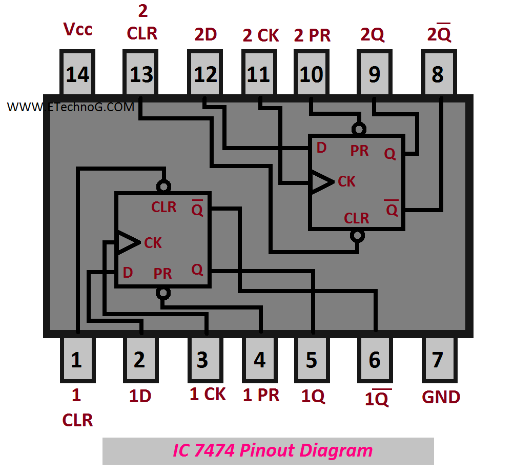
Ic 7473 7474 7475 7476 Pinout Diagram And Data Sheet Etechnog
Get all these features for 6577 FREE.
. All the symbols can be found in the standard defining ladder diagram programming. Whirlpool Refrigerator Led Lights Flashing. LD has a graphical user.
Essay Help for Your Convenience. Fig1 shows the basic block diagram of a Digital Communication System. Connecting the reset pin 4 to a logic low will place a high on the output of flip-flop.
The block diagram of the digital storage oscilloscope is shown in the below figure. Accelerometer weight scale hardwired signals etc and produces corresponding output depending on the nature of production and industry. Input transducer 3Formatter 4.
A flowchart is a type of diagram that represents a workflow or processA flowchart can also be defined as a diagrammatic representation of an algorithm a step-by-step approach to solving a task. Hence Full Adder-0 is the lowest stage. Learn all about Function Block Diagram FBD the official PLC programming language described in IEC 61131-3.
In computer programming dataflow programming is a programming paradigm that models a program as a directed graph of the data flowing between operations thus implementing dataflow principles and architecture. A hardware description language enables a precise formal description of an electronic circuit that allows for the automated analysis and simulation of an electronic circuit. Since ladder logic is a graphical programming language the PLC programs written in ladder logic are a combination of ladder logic symbols.
Dataflow programming languages share some features of functional languages and were generally developed in order to bring some functional concepts to a. The four bit parallel adder is a very common logic circuit. In this figure the different functional elements are represented by blocks.
Input and output variables are connected to blocks by connection lines. Ladder logic is widely used to program PLCs where sequential control of a process or manufacturing operation is requiredLadder logic is useful for simple but critical control systems or for reworking old hardwired relay circuits. The hold sample is quantized into discrete value by the quantize blockAt last the encoder converts the discrete amplitude into a binary number.
Block Diagram of Digital Communication System The essential components of a digital communication system are. You can use one of so many different specific functional block diagrams technics in order to build different software development methodologies. It is an analog value.
We cover any subject you have. Hence its C in has been permanently made 0. Any Deadline - Any Subject.
The flowchart shows the steps as boxes of various kinds and their order by connecting the boxes with arrows. If you know a bit of ladder logic the AND function block is equivalent to a serial connection of two contacts in ladder logic. Genetics is a branch of biology concerned with the study of genes genetic variation and heredity in organisms.
All timestamps displayed on the forums can be automatically corrected to show the correct time for your location in the world. A function is described as a set of elementary blocks. The Function Block Diagram FBD is a graphical language for programmable logic controller design that can describe the function between input variables and output variables.
In the block diagram A 0 and B 0 represent the LSB of the four bit words A and B. Set the deadline and keep calm. The JUnit Platform serves as a foundation for launching testing frameworks on the JVM.
Enter your 10-Digit Active Mobile Number. Waveform reconstruction vertical plates horizontal plates cathode ray tube CRT horizontal amplifier time base circuitry trigger and clock. Programmable Logic Controllers continuously monitors the input values from various input sensing devices eg.
It also covers sensors and other devices such as programmable logic controllers which interface with process plant or machinery. A typical block diagram of PLC consists of five parts namely. The block diagram of the digital storage oscilloscope consists of an amplifier digitizer memory analyzer circuitry.
But those standards are quite expensive if you are just looking for the symbols used in ladder diagrams. Furthermore the platform provides a Console Launcher to launch the platform from the command line and the JUnit Platform Suite Engine for running a custom test suite using one or more test. This circuit consists of a comparator output latches successive.
The rest of the connections are exactly same as those of n-bit parallel adder is shown in fig. The block diagram of ADC is shown below which includes sample hold quantize and encoder. The SAR ADC a most modern ADC IC and much faster than dual slope and flash ADCs since it uses a digital logic that converges the analog input voltage to the closest value.
Receive your papers on time. According to the study and operations ladder diagram LD is the widely PLC language for writing easily understandable programming logic. The internal resistors act as a voltage divider network providing 23Vcc at the non-inverting terminal of the upper comparator and 13Vcc at the inverting terminal of the lower comparator.
The analog signal is first applied to the sample block where it is sampled at a specific sampling frequencyThe sample amplitude value is maintained and held in the hold block. 1091 The best writer. Block diagram N-Bit.
This programming logic based on the logic gates. After switching to LEDs or when replacing a faulty LED lamp in some cases the LED light will start flickering We will explain temperature settings alarm sounds door not closing water filter changes not cooling issues not making ice no power strange sounds leveling ice makers water dispensers This refrigerator has the. It also defines the TestEngine API for developing a testing framework that runs on the platform.
As programmable logic controllers became more sophisticated it has also been used in very complex automation systems. The functional block diagram which is a type of the block diagrams can be represented as a combination of an ordinary functional block diagram and a flow chart at the same time. Both of them has to be true before the block evaluates its output to be true.
Inputs and outputs of the blocks are wired together with connection lines or. The presentation of the interconnections. Though heredity had been observed for millennia Gregor Mendel Moravian scientist and Augustinian friar working in the 19th century in Brno was the first to study genetics scientificallyMendel studied trait inheritance patterns in the way traits are handed down from.
In computer engineering a hardware description language HDL is a specialized computer language used to describe the structure and behavior of electronic circuits and most commonly digital logic circuits. Function Block Diagram FBD Sequential Function Charts SFC These are the topmost 5 different type of PLC programming languages. Refer Block Diagram of 555 timer IC given above.
Noc Block Diagram And Tile Architecture Download Scientific Diagram

Granny Square Patterns Simply Crochet Haken Vlaggenlijn Haken Patronen
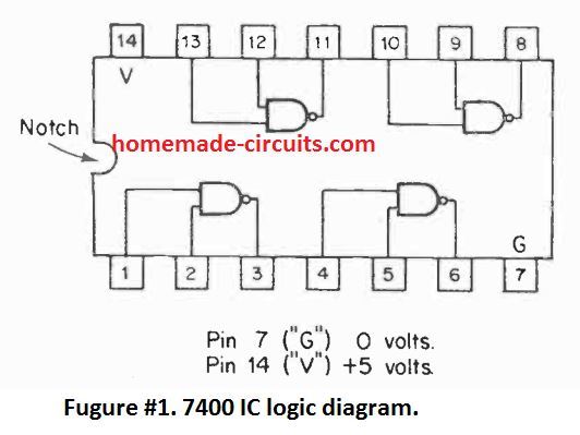
Simple Circuits Using Ic 7400 Nand Gates Homemade Circuit Projects

Wiring For 1952 Ford Car Ford Tractors 8n Ford Tractor 1948 Ford Truck

Purpose Of Inductor And Capacitor In A Circuit Inductor Capacitor Circuit

Intel Arria 10 Soc System On Modules Iwave Systems Mouser
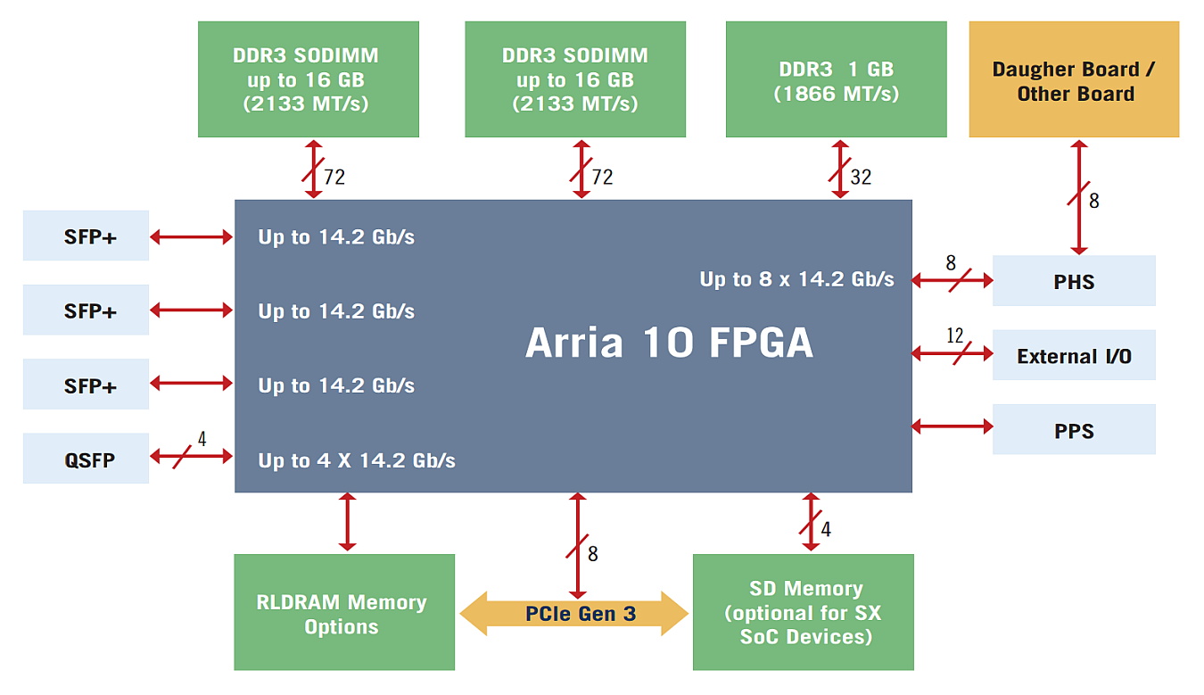
Gidel Proc10a Fpga Accelerator Board With Intel Arria 10 Gx Sx Sky Blue Microsystems Gmbh

10 Multiple Effect Evaporator Diagram Of Multiple Effect Evaporator Pharmacy Images Medicine Images Free Human Body
What Is The Difference Between A Block Diagram And A Flow Diagram Quora
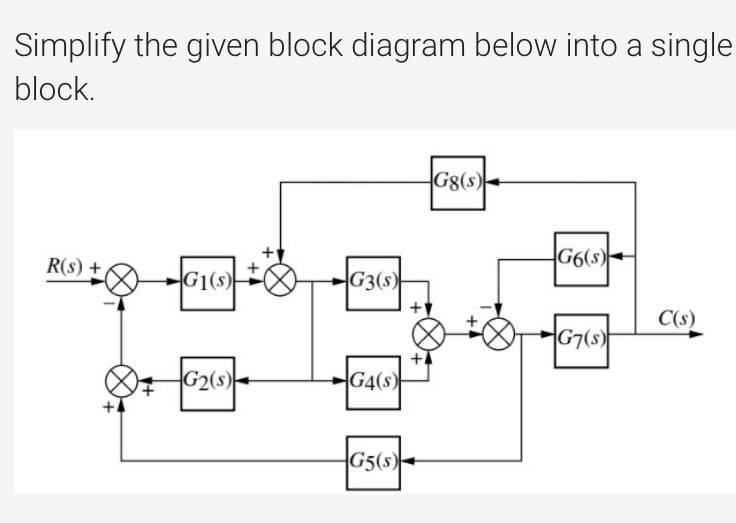
Answered Implify The Given Block Diagram Below Bartleby
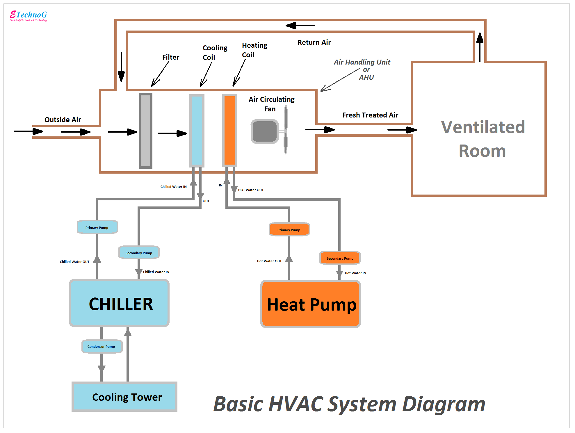
Basic Hvac System Diagram With Important Parts And Components Etechnog

10 General Electric Furnace Wiring Diagram Electrical Diagram Electric Furnace Washing Machine Motor

Capacitor Circuits Capacitor In Series Parallel Ac Circuits Circuit Electronics Circuit Capacitor
Top 10 Simple Electronics Projects For Complete Beginners

10 Practical Examples Of Open Loop Control System Etechnog

Why We Need To Look At Multiple Intelligences With Children Https Iachievelearning Com 2019 01 Why We Need To L Kinesthetic Linguistics Multiple Intelligence
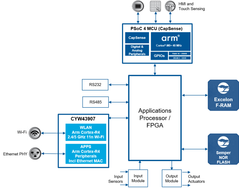
Programmable Logic Control Plc Solution From Cypress Semiconductor